On Sheet- how does a CTC panel work?
On Sheet- how does a CTC panel work?
 ou might have seen my last posting HERE, where we ran Ken Farnham’s Florida East Coast. I mentioned we have fun and I mentioned his railroad is CTC. So let’s look a little closer at how it works.
CTC means “Centralized Traffic Control”. For all that talk I’ve blabbered about TT&TO (Time Table and Train Orders) and Warrants, CTC is one of the newer methods. It requires that signals on the layout can be controlled remotely, and that turnouts have powered relays that can move the points (and also be controlled remotely). The dispatcher, possibly from a desk thousands of miles away, controls all signals and mainline turnouts.
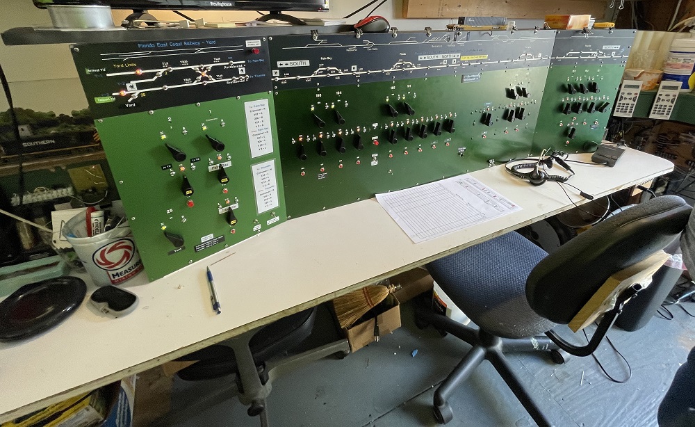
Below is shown the panel that is in use on the FEC. Note that the railroad has a shared staging yard. The trains leave a departure track and go through a crossover to put them onto the south side of the railroad (Palm Bay) or the north side (Titusville). All the yard throat switches and signals are on the left section of the panel (you can see the crossover there). That is it’s own separate part of the railroad and since it is rather unique, I won’t cover that part of the panel. Everything else – the long center section and the right smaller part, those control the layout proper.
My happy place (Photo: John DV)
While it might look complex, it is not. So, the first thing you’ll do is sit in the chair provided. To the right on the desk, there is a head set – put it on. This puts you on a party-line where all the phones in the train room share. There is also a push-to-talk button that puts you on the overhead. I’ll mention that there are also buttons to control weather effects (lighting and thunder) in the other room, and to control the defect detector. Not important.
So, looking at the above picture, you’ll see two track diagrams, two rows of left-right toggles, and then a line of buttons. Let’s go top to bottom.
The top track diagram: This one is pretty faint, but it runs along the top of the panel. This shows a detailed look at the railroad, showing sidings and secondary track. It helps the dispatcher know where the switching areas are. Not every track is shown, but it gives a general idea.
The second track diagram: This is the heavier white line. All it shows is the main line and any sidings controlled by the dispatcher. Note that it does line up with the top system diagram. Set into the lines are occupancy lights (denoting locations of trains). Also, there are lights for each siding turnout, which illuminate of the track is aligned to the siding.
The first row of left-right toggles: These are marked as “N-R” and control the mainline/siding turnouts. If the toggle is pushed left (N) then the turnout is normalized (set for the main). To the right, it’s lined for the siding and a notice-light illuminates on the turnout. You’ll note in the photo that all the toggles are to the left – the tracks are all mainlined from Palm Bay to Titusville.
The second row of left-right toggles: These are marked with “L-R” and are used to control signals. You’ll notice that there are a lot more of them than turnouts. They way they work is simple; in the most basic case (along a mainline) there will be a pair of signals, one facing south, one north, each positioned to the right of the track they indicate for. The main track diagram clearly marks the signal mileposts so you can figure out which toggle controls which set of signals. So, push the lever right (or “R”) and the signal protecting track to the right (i.e. north) will go permissive (green or yellow). Pushing it to the left (“L”) the south direction will get a permissive signal.
So, if you want a train to leave one section of main-siding track, you’ll just flip all the toggles between the origin and destination in the correct direction.
A couple of things I didn’t mention about signals.First, there is a secondary line of buttons, one under each signal. These push buttons are activators (you have to push them to make the signal engage). Until you push them, they stay red. So a lot of times, if I’m waiting for some reason to send a train but must hold him, I might toggle over all the signals I’m going to need but hold off on hitting the activator buttons. When it’s train time, I just run a finger down the line of buttons and the signals all go permissive.
Another point – there are indicator lights (for green and red) just below the “L” and “R” indications. They will show you if each signal is permissive or restrictive. I use these terms because permissive signals might show green or yellow (depending on conditions). On this panel, you just get green.
I mentioned that you might get a yellow signal. Generally, if the next signal is red, the signal before it will go yellow, warning the train to expect a restrictive signal at the next light.
There are also reasons a signal might NOT go permissive, even if you push the toggle over and hit the button. If any of the turnouts are set against you (i.e. into a siding) the block will not clear. You will need to issue the train crew an order to proceed through the red signal, looking for misaligned turnouts.Then you’ll need to look at your logs and figure out who to issue demerits to for leaving a turnout on the main open. Also, you cannot set a signal into an occupied block of track.
Maybe you were thinking about main/siding tracks. Do you have multiple signal levers for main and sidings? After all, you have three signals there – one facing the turnout (and can be routed down the main or into the siding) and two going the other direction, one for the main, one for the siding. No, in this case, you only have one signal toggle. It ties to the turnout toggle to determine which North-South signal you’ll be setting. So, if giving a permissive signal INTO a main/siding turnout, the direction of the turnout will determine which signal on the two-target masthead illuminates (if routed to the main, the top one, if routed to the siding, the bottom one). If sitting on the main or siding facing single track (and with a signal guarding each), the signal that will go permissive is the one the turnout is set to.
It should also be noted that, on this panel, signals drop if a train passes them. So, if I’m running only one train across the division, I can set all the signals green in that direction and watch the train indicator light move across the board. As it passes each signal, the signal indicator will go from green to red. This is why I had such an exciting time when I ended up running four southbound trains, nose to tail. I could not set a signal until the train cleared the block. So I’d be hunched over my panel – as soon as a train moved, I’d light the signal into his departed block, letting the next train enter it. And I had to do this for each of the three trailing trains.From their point of view, they were coming up on yellow lights, not realizing that I was furiously manipulating the activate buttons to keep them moving as blocks cleared. I kept the toggles all to the left – nobody was coming the other way.
I’ll mention in closing that you have a sheet that shows the lineup of trains, a string diagram that notes where (on the timetable) trains should be, a grid of locations vs time. This is critical to maintain during a session – I generally circle the location on the sheet I’ve cleared a train to. The first time I ran a CTC board, I figured the indicator lights would be enough. Of course, those tell you a track is occupied. They don’t tell you who is there. With all this wonderful electronics, you’d better keep a sheet of paper handy to remember who is who.
There. Now you know how to run CTC. Next week, I’ll show you how to play the pipe organ for the Mormon Tabernacle Choir.
>>>AND FOR ALL THIS, YOU SHOULD BUY ONE OF MY BOOKS, DOWN THIS LINK!<<<
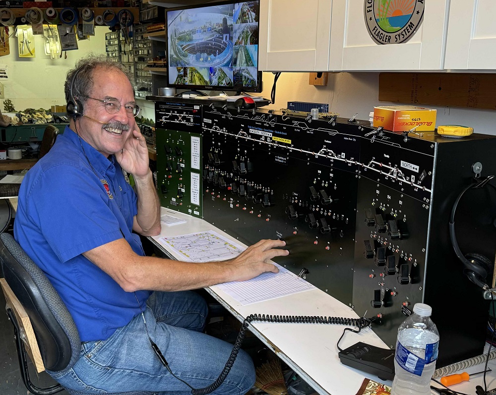
Doing what I do best. Unless you are John DV and think I left you to die in Pinetta) (Photo: Zack B)